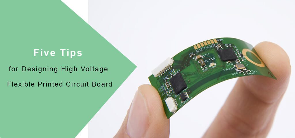
Five Tips for Designing High Voltage Flexible Printed Circuit Board
It is imperative to check a surprising number of parameters before designing a flexible printed circuit board. If not, we will have to discard everything and start again when the flexible circuit board project does not have a good result. You have to be careful when selecting materials for a flexible printed circuit.
At the start of your career as a flexible printed circuit board designer, you may end up getting specialized Flexi circuit projects such as high voltage applications. There are also other dedicated flexibility circuit board applications, and you must begin to consider advanced design requirements.
- Select a suitable material for flexible printed circuit board
The basis of your flexible printed circuit board is the board. Therefore, that is the first material specification to take into account. The material should be suitable for performance requirements and the operating environment, as that will have a significant impact on how the board material ages on the flexible printed circuit board.
For a high voltage flexible printed circuit board design, you must have a board material specially designed to tolerate an over-voltage event and the usual high voltage operating conditions.
Here are some material options to consider for flexible circuit board:
FR4 laminate
FR4 has a very high dielectric degradation. However, it is more porous than BT epoxy resin and polyimide, making plaque contamination easier. It also has a weak edge structure, and as the edge cracks, the dielectric value will decrease. Ageing is a likely difficulty, especially for electronics near the edge. Additionally, FR4 has no recovery or protection from charring that occurs during over-voltage events.
BT Epoxy Resin
A thermosetting resin, BT Epoxy Resin, has durable sidewalls and is best for applications with planar coils and medium-voltage circuits.
Isola, high voltage laminates
There are several high voltage laminates. Isola is one of the best known, extinguishes the arches and leaves a non-conductive base coat. At the same time, that is an incredible performance advantage in high voltage applications. You must understand the design constraints before you start. These laminates usually are quite expensive, and can only produce straightforward single-sided or double-sided plates.
When you start talking about production, get the datasheets for all your options from the manufacturer, and make sure the performance matches your requirements. Also, do not mix and match the insulators on your Flexi circuit board. Mismatch in material properties can eventually cause manufacturing and performance difficulties.
- The bottom side of an empty flexible circuit board
Do not use multiple insulating materials within the layers of your flexible printed circuit board.
- Check the glass and resin content
If the resin content and glass style used on the printed flexible circuit board is a rare sight in the datasheets or manufacturing guides you receive, please ask, especially for them. In a high voltage flexible printed circuit board, it is essential to have a high resin content to minimize the gaps between the foil layers and to change the effective dielectric of your board. It would help if you also use a small glass style to help penetrate the resin.
Voltage gradients are specifically for resin systems in direct current voltage units / thousand. You need to make sure that your voltage gradient is less than the age reduction value of the resin system found between its insulating sheets. For an alternating current voltage gradient, use less than half the direct current gradient value.
- Select the Right Drivers
Once you have resolved the laminate layers and the resin of your Flexi circuit layout, you can proceed to the conductors. The spacing between your tracks and discs is exclusively for safety and standards. You will also want the quality of your copper to meet your requirements. Select a copper weight for your tracks that are suitable for electrical and mechanical stresses. 1-3 ounce copper tracks are prone to failure with any over-current, and 1-2 ounce tracks are susceptible to mechanical stress. Even slight increases in weight improve the survivability of your board.
- Ask about finished surfaces
Lastly, it would be best if you ask your manufacturer about the finish of your board. Poor plate surface conditions, such as bumps, particles, inconsistencies, or contamination, make arches are possible and may override any selection of expensive material. On the conductor, rough spots or scratches will create areas that concentrate the electric field’s strength and have arcs at lower voltages. Ensure that tampering with your plates during production protects them from any damage that may decrease their high voltage performance.

